An LED T8 heat sink is the aluminum section that draws heat from the LED printed circuit board and spreads it through the tube housing. It matters because excessive board temperature accelerates lumen depreciation, shifts color, stresses solder joints, and can shorten driver and LED service life. The profile often doubles as the tube’s structural spine, so its cross-section also affects PCB fit, driver clearance, diffuser attachment, end-cap alignment, and assembly speed.
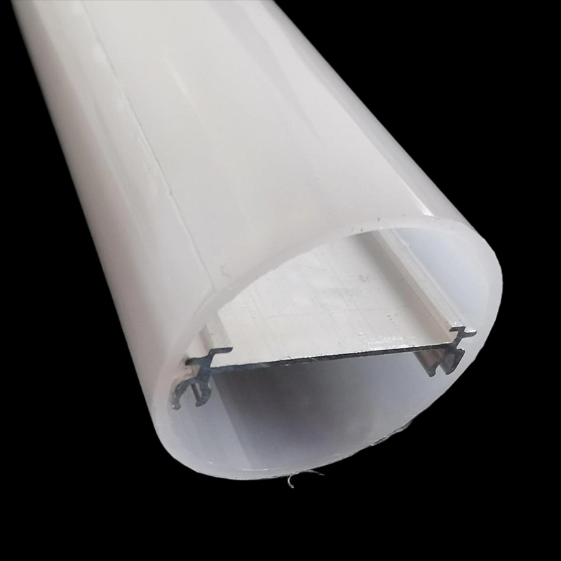
An LED T8 Heat Sink Is the Aluminum Thermal Path That Carries Heat Away From the LED Board
LEDs convert part of their electrical input into heat concentrated around small component packages. That heat must pass from the package into the PCB, across the board-to-profile interface, through the aluminum extrusion, and finally into the surrounding air. A profile with substantial aluminum can still perform poorly if any connection in that path is weak.
The heat sink doesn’t actively cool the tube. It spreads heat over a larger area so convection and radiation can remove it. This is why buyers should assess the complete LED T8 heat sink and housing construction, not compare profiles by weight or appearance alone.
PCB contact, thermal-interface quality, fastening, and extrusion geometry determine whether that path works as intended
The PCB needs broad, consistent contact with the aluminum. Burrs, bowed boards, uneven slots, excessive adhesive thickness, and poorly fitted thermal tape create air gaps that resist heat transfer. Fastening also matters. Clips, retaining channels, screws, or approved thermal adhesive must keep the board seated after repeated heating and cooling.
Extrusion geometry controls how quickly heat spreads away from the LED line. Aluminum thickness beneath the board, the width of the conductive section, and the amount of exposed surface all influence performance. More metal isn’t automatically better: unnecessary mass raises cost and shipping weight, while poorly placed material may contribute little to cooling. The useful question is whether the geometry keeps critical components within their allowable temperatures at the tube’s intended wattage.
Thermal Performance Must Be Verified in the Tube’s Actual Airflow and Mounting Conditions
A bench test in open air is only a starting point. T8 tubes are installed in enclosed troffers, narrow channels, signs, refrigerated cases, and weather-resistant luminaires. Each arrangement changes airflow around the profile. Ambient temperature, LED density, driver placement, diffuser material, mounting orientation, and nearby metalwork can produce materially different results from the same heat sink.
Testing should use a production-representative LED board, driver, thermal interface, diffuser, and end caps. Record ambient temperature, electrical input, mounting orientation, test duration, and measurement locations. Allow the assembly to reach a stable condition rather than reporting an early reading. Board or package-case temperature also shouldn’t be presented as LED junction temperature unless the LED supplier’s approved method supports that conversion.
Document board and housing temperatures under open, enclosed, flush-mounted, and restricted-airflow operation
Measure near the hottest LED region, around the center of the board, beside the driver, and on the external aluminum surface. Open-air operation establishes a baseline. Enclosed and restricted-airflow tests expose heat buildup that a catalog profile drawing can’t predict. Flush mounting may help if the tube has reliable thermal contact with a larger metal fixture, but it may also trap warm air when contact is poor.
The worst case is often not the highest room temperature alone. Driver heat concentrated near one end, insulation around the luminaire, or an upward-facing aluminum section can create a local hot spot. Approval samples should therefore match the intended electrical load and installation condition.
T8 Compatibility Depends on the Cross-Section, Not the Nominal Tube Length Alone
Calling a housing “T8” doesn’t establish that your PCB, driver, end caps, or production fixtures will fit. Two nominally similar tubes can use different board channels, internal ribs, diffuser locks, and end-cap interfaces. Cross-sectional drawings and physical samples should be reviewed before tooling or volume purchasing is approved.
Use JE’s listed 26 mm diameter, 19 × 1 mm PCB fit, up-to-12 mm driver space, and available lengths as screening data before approving drawings and samples
JE lists a 26 mm diameter, support for a 19 × 1 mm PCB, and internal-driver space up to 12 mm for this product category. Listed lengths are 600, 900, 1200, 1500, and 2400 mm, with customized lengths available. These figures help narrow the search, but they aren’t a substitute for a controlled drawing.
Confirm PCB width and thickness tolerances, component height, connector clearance, wire routing, end-cap insertion depth, and the finished lamp length. A nominal four-foot tube commonly points buyers toward the listed 1200 mm option, yet the required extrusion cut length depends on the end-cap design and completed assembly. JE’s T8 housing dimensions and available lengths should be treated as screening information before sample validation. G13 end-cap fit, pin alignment, and rotation resistance need separate checks.
6063 Aluminum, Anodizing, and Assembly Features Solve Different Engineering and Production Problems
JE specifies 6063 aluminum for its LED T8 profiles. This alloy is widely suited to extrusion because it can form the channels, ribs, and relatively thin sections used in tube housings while providing a practical surface finish. Buyers should still specify the required temper, dimensional tolerances, straightness, twist, cut-length tolerance, and surface condition; the alloy number alone doesn’t settle those points.
Anodizing addresses surface protection and appearance. It can improve corrosion and wear resistance and changes the electrical behavior of the surface, but it doesn’t repair poor PCB contact or inadequate aluminum geometry. Scratches, machined ends, screw points, and grounding locations may interrupt the anodized layer, so electrical bonding and insulation decisions must be reviewed as part of the lamp design.
Production details are just as consequential. A well-controlled PCB channel lets operators insert the board without forcing or rocking it. Consistent diffuser locks reduce cracking and rework. Clear and frosted polycarbonate components serve different optical requirements, while internal ribs can guide wires or separate them from sharp edges. Those features often save more labor than a small reduction in extrusion price.
Common Buyer Questions About Four-Foot Profiles, Plastic-Clad Housings, Custom Extrusions, and IP65 Claims
Is a 1200 mm profile automatically correct for a four-foot tube? No. It is a common starting length, but the final dimension depends on end caps, pin position, assembly method, and the customer’s fixture. Approve the finished lamp drawing rather than ordering from the nominal tube description.
Does plastic-clad aluminum cool as well as exposed aluminum? Not necessarily. In a plastic-clad aluminum T8 tube housing, the aluminum remains the main conductive path while the plastic provides optical coverage, isolation, or external form. Plastic over the aluminum can affect heat release, so the complete assembly requires testing at rated power.
When does a custom extrusion make sense? Private tooling is justified when a public mold can’t accommodate the PCB, driver, optical geometry, end-cap interface, or production method. Tooling approval should include cross-section dimensions, trial-extrusion samples, straightness, bow, twist, surface finish, and mating-part checks. A custom die doesn’t eliminate normal extrusion variation.
Does an IP65 housing make the finished tube IP65? No. JE lists IP20 and IP65 assembly options, but the ingress rating applies to a tested assembly, not the aluminum profile by itself. End-cap seals, joints, cable entries, adhesives, diffuser engagement, and production consistency all contribute. Any rating claim must match the final configuration and applicable test evidence.
These profiles also have limits. A high-output board in a sealed fixture may exceed the capacity of a compact T8 extrusion, even with good assembly. In that case, reduce thermal load, change the cross-section, improve the installation’s heat path, or use a different luminaire architecture.
Decision Checklist: Approve Thermal Evidence, Component Fit, Tolerances, Samples, Compliance Boundaries, and Commercial Terms
- Review thermal results from the intended PCB, driver, diffuser, end caps, power level, orientation, and airflow condition.
- Confirm the 26 mm envelope, 19 × 1 mm PCB fit, driver clearance, wire routing, and G13 end-cap interface against controlled drawings.
- Specify aluminum temper, anodized finish if required, straightness, twist, critical cross-section dimensions, and cut-length tolerances.
- Build pilot samples and check PCB insertion, diffuser engagement, end-cap alignment, thermal-interface placement, and worker handling time.
- Define which party is responsible for electrical safety, ingress testing, material compliance, and finished-lamp certification.
- Compare public-mold and private-mold costs, tooling ownership, minimum order quantities, sample approval terms, packaging, and acceptable inspection criteria.