- English
- Español
- Português
- русский
- Français
- 日本語
- Deutsch
- tiếng Việt
- Italiano
- Nederlands
- ภาษาไทย
- Polski
- 한국어
- Svenska
- magyar
- Malay
- বাংলা ভাষার
- Dansk
- Suomi
- हिन्दी
- Pilipino
- Türkçe
- Gaeilge
- العربية
- Indonesia
- Norsk
- تمل
- český
- ελληνικά
- український
- Javanese
- فارسی
- தமிழ்
- తెలుగు
- नेपाली
- Burmese
- български
- ລາວ
- Latine
- Қазақша
- Euskal
- Azərbaycan
- Slovenský jazyk
- Македонски
- Lietuvos
- Eesti Keel
- Română
- Slovenski
- मराठी
- Srpski језик

What Is a Double-PCB T12 LED Tube Housing?
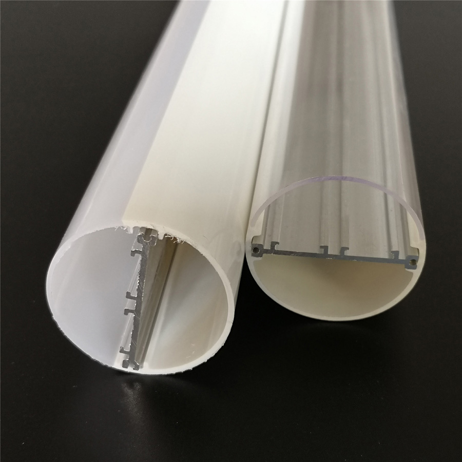
A double-PCB T12 LED tube housing is an outer polycarbonate tube combined with an internal aluminum profile that holds two LED circuit boards. JE’s JE-34 housing uses a 38 mm diameter tube, two 10 × 1.0 mm PCB positions, and space for an internal driver up to 16 mm high. It can be configured for IP20 or IP65 construction, with lengths from 600 mm to 2400 mm or made to a custom length.
That makes it a housing for OEM tube assembly, not a complete LED lamp. Your team still selects the LEDs, PCB layout, driver, wiring, end-cap sealing method, and final electrical configuration. The housing gives those decisions a defined mechanical starting point.
See the full LED T12 plastic tube and double circuit board aluminum housing specification before preparing a sample request.
What does the JE-34 T12 housing include for OEM tube assembly?
The JE-34 T12 LED tube housing includes a polycarbonate outer tube, an internal 6063 aluminum profile, two PCB mounting positions, plastic end caps, and room for an internal driver. The outside tube can be clear or frosted, and the diffuser thickness is listed from 0.6 mm to 2.0 mm.
The standard diameter is 38 mm. Available tube lengths are 600 mm to 2400 mm, with custom lengths available for qualified projects. Those dimensions should not be treated as a complete mechanical drawing, however. PCB seating, end-cap engagement, lead routing, and driver clearance still need to be checked against your actual components.
For an OEM buyer, the key point is that JE supplies the extruded plastic and aluminum housing system for your assembly line. JE operates plastic and aluminum extrusion lines, mold-making, testing, sample approval, and mass-production quality control for LED profile projects.
How do two PCB channels and an internal aluminum profile expand the design space?
Two PCB channels let you distribute LEDs across two boards instead of forcing every LED, driver connection, and thermal interface onto one narrow circuit board. That creates more room for lamp wattage and layout decisions, but it does not guarantee a specific wattage. The final limit depends on LED type, board construction, current, driver selection, thermal testing, and the completed assembly.
Dual 10 × 1.0 mm PCB positions, internal driver clearance, and thermal support
Each PCB position is specified at 10 × 1.0 mm. Confirm that your board width and thickness match those positions before tooling or sample approval. A board that fits the nominal channel but shifts during assembly can create uneven light, wiring pressure, or poor contact with the aluminum profile.
The internal driver space is listed at up to 16 mm in height. Measure the driver body, insulation, connectors, and any strain-relief parts—not only the driver label. Clearance that looks acceptable on a component drawing can disappear once wires are bent inside the tube.
The aluminum profile provides a metal structure beneath the PCBs and can help move heat away from the boards. It is not a substitute for thermal validation. Test the complete lamp with the chosen LEDs, PCB, driver, end caps, and installation orientation.
Why the 6063 aluminum insert helps separate heat management from light diffusion
The 6063 aluminum insert and the polycarbonate tube perform different jobs. The aluminum profile supports the circuit boards and offers a more suitable path for heat transfer than plastic alone. The polycarbonate tube forms the visible outer body and diffuser, protecting the internal parts while shaping the lamp’s appearance.
This separation is useful in a T12 LED tube housing with an aluminum insert because the optical cover can be selected for appearance and transmission without asking the plastic to carry the entire mechanical and thermal load. Actual thermal results still depend on contact between the PCB and profile, assembly pressure, LED spacing, driver output, and airflow around the finished tube.
Which PCB, driver, length, and optical details should be approved before sampling?
Approve the mechanical drawing together with the electrical and optical parts list. A housing sample is only useful if it represents the assembly you plan to produce.
Confirm PCB spacing, driver height up to 16 mm, tube length, end-cap fit, and wiring clearance
- PCB fit: Confirm the two 10 × 1.0 mm board positions, board edge clearance, and how the boards are retained during assembly.
- Driver package: Check the complete driver height against the available space up to 16 mm, including terminals, sleeves, and wires.
- Tube length: Select a length from 600 mm to 2400 mm or submit the required custom length. Account for the end caps and the usable internal assembly length.
- End caps: Approve the plastic end-cap dimensions, attachment method, cable exit, and gasket or seal arrangement if the lamp will use an IP65 construction.
- Wiring: Confirm where input wires enter, how they turn inside the tube, and whether the driver or PCB connections can be assembled without pinching insulation.
These checks prevent a common sampling mistake: approving the tube diameter while leaving the end-cap and driver interface unresolved.
Choose clear or frosted polycarbonate based on transmission, glare, and appearance requirements
JE lists light transmission above 95% for clear covers and above 85% for milky white covers. Clear polycarbonate preserves more output but shows internal LED points more readily and may produce more visible glare. A milky or frosted cover softens the appearance and hides components better, with some reduction in transmission.
Choose the cover after reviewing the LED pitch, required visual uniformity, viewing angle, and target appearance. The listed transmission figures describe the cover option; they do not predict the delivered light from your complete lamp. Ask for the relevant diffuser sample if optical appearance is a major requirement.
When is an IP20 construction suitable, and when is IP65 sealing necessary?
IP20 is generally suited to dry indoor installations where the tube is protected from water and the enclosure does not need sealed construction. It is a practical choice for many interior fixtures, but the final application still determines whether the open or non-sealed arrangement is acceptable.
Use the IP65 construction option when the finished fixture may encounter dust or water jets and the project requires that level of enclosure protection. The housing alone does not establish the final IP rating. Seals, end caps, cable entries, driver placement, assembly tolerances, and production inspection all affect the result. Confirm the required test method and have the completed lamp evaluated rather than assuming an IP65 housing automatically makes the entire fixture IP65.
Is JE supplying a complete LED tube or a housing for your own assembly?
JE is supplying the LED tube housing system for OEM and ODM assembly, not a finished, electrically certified tube unless a separate project agreement defines those additional services. You provide or approve the LED boards, driver, wiring, and final lamp configuration.
That arrangement suits lighting manufacturers that need a T12 plastic LED tube housing with an aluminum insert and want control over the electronics. It may not suit a buyer looking for a ready-to-install, fully assembled replacement lamp. Clarify supply scope, testing responsibility, labeling, and regulatory requirements before placing a production order.
For custom assembly requirements, review the custom T12 LED tube housing details with JE’s engineering team.
How should US OEM buyers move from drawing review to samples and production?
Send JE the tube length, PCB drawings, driver dimensions, wire-exit plan, end-cap requirements, optical preference, and required IP construction. Include the installation environment and target assembly process. If the two boards use different LED layouts or serve different optical zones, show that clearly in the drawing.
JE can then review the extrusion and tooling requirements, prepare samples, and confirm the mechanical interfaces before mass production. Use the sample to check board fit, driver clearance, wire routing, diffuser appearance, end-cap retention, and—where applicable—the sealing process for the IP65 version.
Start with the JE-34 T12 double-PCB housing page, then contact JE with your drawings and target quantity. The earlier those project inputs are fixed, the less likely a low-cost housing decision becomes an expensive assembly change later.