JE’s T8 double-sided LED tube housing is an empty enclosure platform for OEM linear-lighting projects. The confirmed configuration has a 26 mm outside diameter, two 12 × 1 mm PCB positions, an internal 6063 aluminum profile, a clear or frosted polycarbonate enclosure, plastic end caps, and an external-driver layout. Standard or customized lengths are available from 600 mm to 2400 mm, with IP20 and IP65 configurations offered.
The key word is housing. This product does not become a working lamp until the LEDs, PCB assemblies, wiring, driver, end termination, and any required seals have been selected and integrated. Buyers should therefore evaluate it from a controlled drawing and an assembled sample—not from the T8 name alone. Review the current T8 double-sided luminous housing before sending your PCB and project requirements to JE.
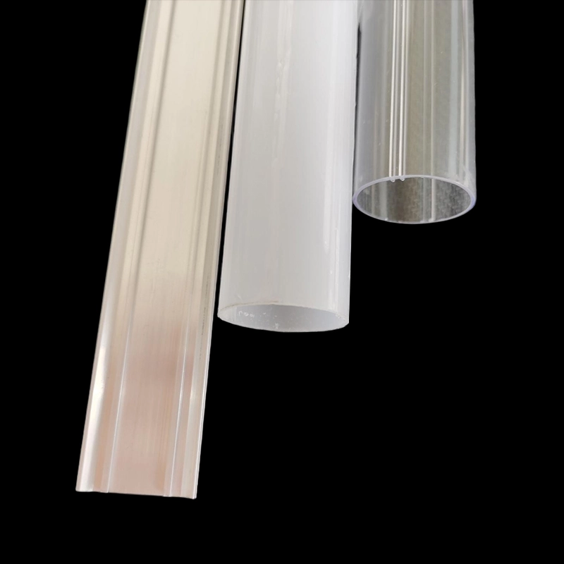
The Product Is an Empty OEM Housing, Not a Finished T8 Lamp or Fluorescent Replacement
“T8” identifies the general tube format, but it does not establish electrical or mechanical compatibility with an existing fluorescent fixture. A 26 mm housing may look familiar while using completely different boards, wiring, end caps, mounting details, and power architecture.
Do not assume that it accepts a conventional fluorescent ballast, fits a G13 lampholder, includes mains-rated pins, or can replace an installed lamp one-for-one. None of those details are confirmed by the housing diameter. If retrofit compatibility is required, put the base geometry, pin arrangement, overall lamp length, electrical input, wiring mode, and fixture interface on the approval drawing.
This distinction also affects purchasing. The housing specification identifies the extrusion and enclosure package. It does not, by itself, define LED quantity, color temperature, light output, optical distribution, power, driver behavior, dimming, surge protection, operating temperature, or service life. Those are finished-luminaire decisions controlled by the buyer’s component design and qualification program.
Cross-Section of the Double-Sided T8 Housing Assembly
The assembly combines a round polycarbonate body with an internal aluminum profile. Within that cross-section are two PCB positions, each identified as 12 × 1 mm. This arrangement gives an OEM designer two mounting locations for LED boards inside one 26 mm tube envelope.
The aluminum insert provides a defined internal structure for the PCB locations. It may also participate in heat transfer from the boards, but thermal performance cannot be inferred from the alloy name or profile alone. LED loading, board construction, thermal-interface material, contact quality, driver losses, ambient temperature, tube orientation, and airflow all affect operating temperature. Approve the thermal design with the intended LED boards installed.
How the paired PCB positions support two luminous faces
Two PCB positions allow LEDs to be arranged toward two sides of the tube instead of relying on one board to illuminate the entire circumference. That can suit bidirectional linear lighting, suspended luminaires, display lighting, transit interiors, and other installations where light is needed in more than one direction.
The extrusion does not guarantee a specific beam angle or an equal 50/50 light split. Actual distribution depends on the orientation of the PCB positions, LED package, diode spacing, board width, distance to the polycarbonate, diffuser finish, internal obstruction, and nearby luminaire surfaces. Clear PC tends to preserve LED definition and output direction; frosted PC mixes the light more effectively but can reduce visible intensity and soften beam control.
Before tooling or production approval, inspect an illuminated sample from both sides. Look for LED imaging, dark bands near the aluminum insert, color variation, end shadows, and differences in brightness between the two faces. Photometric testing belongs at the finished-luminaire level because the empty housing contains no light source.
Confirm the supplied housing components versus buyer-specified LEDs, PCB assemblies, wiring, driver, and seals
A housing quotation should separate JE-supplied parts from buyer-supplied electrical components. Based on the published product description, the enclosure can include the internal 6063 aluminum profile, clear or frosted polycarbonate, and plastic end caps. The architecture uses an external driver. Exact packing contents, end-cap style, hardware, seals, cable-entry parts, and assembly services should still be listed line by line in the quotation.
The buyer normally needs to define the LED boards, LEDs, wiring, connectors, thermal-interface material, driver, grounding method where applicable, and final electrical terminations. For an IP65 target, the responsibility for gaskets, sealant, cable glands, end-cap sealing, and assembly process must be especially clear. An IP65-capable set of parts is not automatically an IP65 luminaire after uncontrolled field assembly.
Specification Matrix for Drawing and Component Review
Use the following matrix as the starting point for drawing review. Published values identify the available product configuration; they do not replace project-specific tolerances, fit checks, or regulatory review.
| Parameter | Published configuration | What the buyer should approve |
|---|---|---|
| Product type | Empty T8 double-sided LED tube housing | Scope of supplied mechanical parts and excluded electrical components |
| Outside diameter | 26 mm | Diameter tolerance, straightness, mating clearances, and fixture fit |
| PCB positions | Two positions, each 12 × 1 mm | Actual PCB thickness and width, insertion clearance, retention, and thermal contact |
| Internal metal profile | 6063 aluminum | Profile cross-section, finish if required, temper if material-critical, cut length, and burr limits |
| Outer enclosure | Clear or frosted polycarbonate | Optical appearance, diffusion, color consistency, impact requirements, and environmental suitability |
| End termination | Plastic end caps | Cap geometry, attachment method, cable exit, connector or pin details, and sealing responsibility |
| Driver arrangement | External driver | Driver location, wiring route, connector system, strain relief, and electrical ratings |
| Ingress configuration | IP20 or IP65 option | Complete sealing design, assembly instructions, and finished-unit test method |
| Length | Standard or customized, 600–2400 mm | Cut-length tolerance, overall assembled length, end allowance, and packaging limit |
Fixed geometry: 26 mm diameter and two 12 × 1 mm PCB positions, with fit and tolerances approved on the drawing
The 26 mm diameter and paired 12 × 1 mm PCB positions are the core geometry, but nominal dimensions are not enough for release. A board designed at the same nominal width as its slot can bind if board fabrication, extrusion, bow, coating, and assembly tolerances stack in the wrong direction. A loose fit creates a different problem: board movement, inconsistent thermal contact, or visible misalignment behind the diffuser.
Send JE the actual PCB outline rather than only writing “12 mm board” in the RFQ. Include PCB thickness, edge finish, solder-mask or coating buildup near the insertion area, component keep-out zones, connector protrusions, and the intended insertion direction. The approved drawing should identify the dimensions that are critical to fit and state how those dimensions will be inspected.
Construction and options: internal 6063 aluminum profile, clear or frosted polycarbonate, plastic end caps, external driver, and 600–2400 mm lengths
6063 is commonly used for extruded aluminum profiles because it can be formed into controlled cross-sections and accepts common finishing processes. Still, “6063 aluminum” is not a complete thermal or mechanical specification. If temper, surface treatment, conductivity, appearance, or corrosion behavior matters to the project, add the requirement to the drawing and request confirmation.
Length also changes more than the purchase price. Long housings are more sensitive to straightness, handling damage, PCB insertion, wiring access, and package design. Confirm whether your specified length refers to the cut extrusion, the polycarbonate body, or the overall assembled unit including end caps. JE lists standard and custom-length T8 LED tube housing options from 600 mm through 2400 mm; the quotation should identify the exact finished length and tolerance.
Clear or Frosted PC, End-Cap Termination, and IP20 or IP65 Configuration Choices
Choose clear polycarbonate when LED visibility, directional output, or the appearance of the internal boards is acceptable. It can reveal diode spacing, wiring, joints, and small alignment errors, so the internal build must be visually clean. Choose frosted PC when you need better visual mixing and less direct LED imaging. Frosting is not a substitute for adequate LED spacing or optical testing, and its effect on transmission should be evaluated with the real light engine.
End caps often become the overlooked interface. They determine how the tube closes, how wires leave the housing, and how the assembly connects to the surrounding luminaire. A plastic end cap should not be assumed to provide a standardized fluorescent base or a waterproof seal. Put the retention method, cable opening, connector arrangement, polarity marking, strain relief, and service-access requirements on the drawing.
IP20 is appropriate only where the completed design does not require protection against water ingress. The IP65 option is intended for a dust-tight and water-jet-resistant configuration, but the rating applies only after the full enclosure system and assembly method have been defined and tested. End-cap joints, cable entries, seal compression, cut surfaces, and production workmanship can all cause leakage.
Ask how the quoted IP20 or IP65 T8 housing configuration differs in components and assembly. If JE supplies loose parts for your factory to assemble, agree on seal materials, sealant location, cure conditions where relevant, cap insertion or fastening method, and the finished-product ingress test. Do not print an IP claim based solely on an unassembled housing sample.
Application Boundaries for Transit, Commercial, Architectural, and Protected Outdoor Luminaires
The double-sided format can support rail-vehicle interiors, stations, commercial lighting, garages, schools, factories, and other linear installations. These uses do not share one qualification standard, so the application name should never stand in for engineering requirements.
Rail-vehicle lighting may require project-specific checks for vibration, shock, flame and smoke behavior, electrical safety, electromagnetic compatibility, material traceability, and secure retention. The 26 mm housing geometry does not prove compliance with any of those requirements. Give JE the required test or material-document list before sampling so that unavailable evidence is discovered early rather than during customer submission.
For commercial and architectural luminaires, buyers usually need to focus on appearance, light distribution, mounting integration, driver access, heat, cleaning, and maintenance. Frosted PC can hide individual LEDs, but a long luminous line can still show dark zones at board joints or end caps. Build a full-length sample if continuous appearance matters; a short offcut will not reveal every production issue.
Garages, factories, and protected outdoor locations add dust, moisture, cleaning practices, temperature variation, and possible chemical exposure. IP65 addresses ingress under defined test conditions, not UV resistance, chemical compatibility, condensation, impact resistance, or unrestricted outdoor exposure. Those properties must be specified and verified separately. If the tube will sit inside another sealed luminaire, also consider trapped heat and whether the external driver remains accessible.
Approval Evidence: Drawings, Sample Inspection, Test Methods, Material Documents, and UL or ETL Submission Support Without a Housing Certification Claim
A credible approval package starts with a controlled cross-sectional drawing and an assembly drawing. They should show the 26 mm diameter, PCB positions, key interfaces, material callouts, end-cap details, length definition, and revision status. Dimensions that affect PCB insertion, cap fit, mounting, or sealing deserve explicit tolerances rather than a general note.
Sample inspection should cover dimensions and practical assembly. Insert the actual PCBs, route the intended wires, fit the end caps, and check the complete length for bow, twist, scratching, color variation, cap gaps, and board movement. Then operate the intended LED and driver system under representative conditions to evaluate temperature and optical appearance.
Test methods need to be agreed before results are compared. For an IP65 design, identify whether testing applies to JE’s assembled sample or to your finished luminaire, including your cable entry and wiring. Material documents may include declarations, datasheets, or test reports, but their availability and relevance must be confirmed for the exact resin, aluminum specification, color, and production configuration being purchased.
UL or ETL submission support should be treated as document coordination, not as a blanket certification claim. A material record, component file, or supplier declaration does not make the empty housing—or the finished lamp—UL Listed or ETL Listed. The final construction, electrical components, temperatures, spacings, wiring, enclosure, and intended use may all be reviewed by the selected certification body.
Tell JE which submission route and documents your lab or certification partner requires. JE can then confirm what is available for the proposed materials and configuration. If a specific recognition, listing, flammability classification, file number, or test report is mandatory, obtain and verify that evidence before approving the order. Never infer it from a logo, a generic material family, or a previous project.
From Drawing Review to Sample Approval and Production Quotation
China offers deep extrusion capacity, but factory location alone tells you little about drawing control, component fit, or repeatability. JE manufactures aluminum and plastic extrusions for LED lighting, including tube housings, LED profiles, PC tubes, end caps, and tri-proof housings. For this project, the useful evidence is a responsive drawing process, a representative sample, a defined inspection plan, and a quotation that makes the supply boundary clear.
Customization workflow: drawing revision, DFM feedback, mold selection, sample verification, and production quality control
Start with the application rather than a loose request for “T8 housing.” Send the PCB files, target overall length, optical preference, end termination, ingress target, mounting interface, and mandatory documents. JE can compare those inputs with an existing public mold or determine whether a private mold and custom extrusion are needed.
During drawing revision, resolve board clearance, end-cap engagement, wire routing, component keep-out areas, sealing surfaces, and visible cosmetic zones. DFM feedback should identify dimensions that are difficult to hold or inspect and any change that affects tooling, assembly, or cost. A custom profile can solve a genuine interface problem, but it also adds tooling approval and locks the project to a new cross-section. Do not order private tooling merely to avoid adapting a noncritical PCB edge.
The sample should represent the agreed material, diffuser finish, aluminum cross-section, end-cap design, and length closely enough to test the real risks. Record any accepted deviation. Once the sample passes dimensional, assembly, optical, thermal, and applicable ingress checks, freeze the drawing revision used for the production quotation.
Production quality control should be tied to observable requirements: material identity, critical cross-sectional dimensions, cut length, straightness where specified, surface condition, diffuser appearance, end-cap fit, PCB insertion, and packaging protection. For sealed assemblies, define how ingress performance is checked and at what sampling level. The quotation should also state tooling ownership where applicable, sample charges, order quantity, lead-time basis, packing method, and shipping terms rather than leaving those points to email assumptions.
RFQ checklist: length, PCB geometry, diffuser, IP target, end caps, tolerances, quantity, packaging, destination, and required documentation
- Length: Specify the cut length and required overall assembled length within the available 600–2400 mm range.
- PCB geometry: Attach board width, thickness, outline, connector position, component keep-outs, and insertion direction.
- Diffuser: Select clear or frosted PC and describe the optical appearance you need the sample to demonstrate.
- IP target: State IP20 or IP65, who performs final assembly, and which finished configuration will be tested.
- End caps: Define termination, cable exit, connector or pin requirements, retention, sealing, and strain relief.
- Tolerances: Mark critical dimensions for PCB fit, cap engagement, mounting, length, and mating parts.
- Quantity: Give prototype, pilot, and expected production quantities so public-mold and custom-mold routes can be compared.
- Packaging: Identify surface-protection needs, bundle limits, labeling, and any length-related handling restrictions.
- Destination: Provide the delivery country, city or port, preferred shipping terms, and any import-document requirements.
- Documentation: List drawings, inspection reports, material records, declarations, test evidence, and certification-submission documents required for approval.
Send that package with your drawing revision to request a sample plan and production quotation for the 26 mm double-sided T8 LED tube housing.