Short answer: the T5 label alone does not guarantee that a diffuser will fit
No. “T5” identifies a nominal tube size class, not a standardized diffuser interface. A replacement cover can have the expected outside diameter and still fail because its snap legs, rails, wall thickness, curvature, or end profile don’t match the housing.
This is the purchasing mistake that causes most avoidable rework: buyers search for a T5 LED tube diffuser replacement, compare one diameter, and assume the cover will clip into the existing extrusion. In practice, the mating cross-section controls compatibility. Before ordering production quantities, compare dimensioned drawings and test a physical sample of the selected T5 diffuser and tube housing.
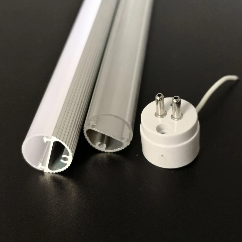
Confirm whether you need a diffuser cover, an empty housing, or a complete tube assembly
Start by defining the component scope. “T5 diffuser” is used loosely in RFQs, and suppliers may interpret it as a polycarbonate lens, a plastic tube, or a housing set. An empty LED T5 tube housing may include the cover and aluminum profile but exclude the PCB, LEDs, driver, wiring, and end caps. A complete tube assembly includes electrical components and requires a much broader technical review.
A diffuser also isn’t a fluorescent-to-LED conversion kit. If the project involves a fluorescent retrofit, mechanical fit is only one issue. Lampholders, wiring, driver architecture, heat management, electrical protection, and the applicable U.S. safety requirements must be evaluated separately.
How a removable polycarbonate cover differs from a half-aluminum, half-plastic housing
A removable polycarbonate cover is the optical part that sits over the LEDs. It may slide into rails or snap onto retaining features in an aluminum or plastic base. Its cross-section must match those features closely enough to hold without rattling, bowing, or requiring damaging assembly force.
A half-aluminum, half-plastic housing is a system of parts. The aluminum section can provide the PCB mounting surface and heat path, while the plastic or polycarbonate section encloses and distributes the light. Buying only the PC cover won’t solve a mismatch in the aluminum profile, PCB location, or end caps.
JE-23 case study: a 15 mm housing for a 10 × 1 mm PCB, not a universal T5 fit standard
JE describes JE-23 as a 15 mm-diameter, half-aluminum and half-plastic housing with a polycarbonate cover. It is designed for a 10 × 1 mm PCB and is offered with clear, frosted, or striped cover options. Those figures describe that housing design; they do not establish a universal interface for every 15 mm T5 diffuser.
The useful lesson is specificity. A buyer evaluating this 15 mm T5 housing reference should compare the complete cross-section, not transfer its dimensions to another supplier’s extrusion. Even a PCB with the stated width can interfere if components extend beyond the board edge or rise into the cover’s internal space.
Use a repeatable fit check from the tube cross-section to the end caps
Work from a drawing, an actual housing sample, and the intended assembly sequence. A tape measure is adequate for rough length checks, but it won’t resolve small retaining lips or groove dimensions. Use suitable precision measuring tools, record where each dimension was taken, and ask the supplier which dimensions are controlled during extrusion.
If the original drawing is unavailable, send a clean cross-section sample rather than photographs alone. Perspective, glare, and translucent plastic make image-based measurements unreliable.
Measure tube diameter, PCB width, cover-to-base mating geometry, and internal clearances
Check the outside diameter at several positions because an old plastic cover may be oval, bowed, or heat-deformed. Then measure the aluminum base, PCB channel, board width and thickness, retaining rails, groove openings, snap-leg spacing, engagement depth, and the radii where the cover meets the base.
Internal clearance deserves equal attention. Map the tallest LED packages, connectors, solder joints, wire exits, and any driver components beneath the diffuser. A cover that clears a bare PCB may rub a connector or press on an LED after assembly. Contact points can create visible shadows, stress the board, or prevent the cover from seating fully.
Verify finished length, cut tolerance, end-cap engagement, driver placement, and assembly method
Housing length and finished luminaire length aren’t necessarily the same. Determine whether the specified length refers to the extrusion, diffuser, assembled tube, or end-cap-to-end-cap dimension. JE lists standard housing lengths from 600 mm through 2400 mm and also offers customization, but the ordered cut length still has to account for the actual end-cap design.
Confirm whether the cover slides in from one end or snaps on from above. A slide-in cover needs assembly clearance and may be blocked by a preinstalled driver or connector. A snap-on cover needs enough flexibility for installation without permanent whitening or cracked retention features. For a nonstandard interface, private-mold extrusion means tooling is made for the customer’s defined profile; it should be approved from drawings and samples before volume production.
Choose clear, frosted, or striped polycarbonate by light-distribution requirements
Optical finish can change both appearance and perceived brightness, so don’t treat it as a cosmetic afterthought.
| Cover | Typical reason to select it | Main trade-off to inspect |
|---|---|---|
| Clear | Maximum visibility of the LEDs or a defined optical system behind the cover | Individual LED points, wiring, and board irregularities remain visible |
| Frosted | Better visual blending and reduced direct view of components | Light output and beam character can change with diffusion level and wall section |
| Striped | Directional light control or concealment through a patterned surface | Stripe orientation and alignment can create an uneven appearance |
Compare samples using the production LED pitch, drive condition, reflector or aluminum base, and viewing distance. A frosted T5 diffuser that looks uniform over a low-output strip may still show hot spots over brighter or widely spaced LEDs.
Use a physical sample to expose loose retention, stress, interference, gaps, and visible hot spots
A drawing narrows the risk; a sample exposes the assembly behavior. Cut the sample with the intended production method, install the real PCB and wiring, and fit the specified end caps. Then check the full length rather than judging a short section alone.
- Install and remove the cover several times using the planned assembly method. Look for cracking, stress whitening, excessive force, or damaged snap features.
- Inspect both seams for continuous engagement. Local gaps often indicate cover bow, profile twist, internal interference, or mismatched retaining geometry.
- Rotate and lightly handle the assembly. Rattle or cover movement points to inadequate retention, even if the part initially appears to fit.
- Power the intended LED board and inspect for hot spots, shadows, color variation, and visible components from realistic viewing angles.
- Fit both end caps and confirm that they retain the diffuser without pushing it out of its grooves or changing the required finished length.
Sample approval should identify the exact material, finish, drawing revision, and supplier tooling. An unlabeled sample is poor protection against a later substitution.
Final go-or-no-go checklist: approve component scope, dimensions, finish, sample fit, drawings, tolerances, and applicable compliance evidence
- Component scope: State whether you’re buying only the PC cover, an empty tube housing, or a complete LED assembly.
- Cross-section: Approve the outside diameter, mating rails or snap features, PCB channel, wall geometry, and internal clearances.
- Length: Define whether the dimension applies to the cut profile or the finished end-cap-to-end-cap assembly.
- Optical finish: Approve clear, frosted, or striped material using the intended PCB and viewing conditions.
- Sample fit: Reject parts that rattle, require damaging force, show open seams, interfere with components, or produce unacceptable hot spots.
- Production controls: Put drawing revisions, critical tolerances, cut requirements, and packaging expectations on the purchase documentation.
- Tooling ownership: For public-mold or private-mold profiles, document which tooling and approved cross-section will be used for production.
- Compliance evidence: Request material and product documentation applicable to the exact U.S. use case. Don’t infer compliance from another profile or from polycarbonate material alone.
- Release decision: Place the production order only after the drawing and a representative custom-length T5 diffuser sample match the approved housing, end caps, PCB, and assembly process.